Measuring CO2 with MH-Z19B on ESP32 with MicroPython
In the previous posts, I described a simple weather station that measures temperature and humidity and sends the measurements to a Google sheet. The system is supposed to be used at home. Therefore, one of the next possible improvements can be measuring air quality in a room. That can be done, for example, by adding an MH-Z19B sensor for measuring CO2 level. We’ll use again a ESP32 board and MicroPython.
Preparation
The device is based on a simple weather station that I described in the following two posts:
Here is a list of old features:
- Measuring temperature and humidity with DHT22 sensor
- Connecting to a Wi-Fi network
- Sending the measurements to a Google sheet
- Configuring the device via a web form
And here is a few new ones:
- Measuring CO2 level with MH-Z19B sensor
- Reporting network connection status, errors and high CO2 level with LEDs
The code is available on GitHub. This post talks about the 1.2.0 release. Make sure that you use this version:
git clone https://github.com/artem-smotrakov/esp32-weather-google-sheets
cd esp32-weather-google-sheets
git checkout 1.2.0
Hardware
Here is a list of components:
- ESP32 development board
- DHT22 sensor
- MH-Z19B sensor
- Switch
- 10 KOhm resistor
- 22 KOhm resistor
- 470 Ohm resistor x3
- LED x3 (blue, red, yellow)
- Breadboard
- Wires
The blue LED means that the device successfully connected to a specified Wi-Fi network. The red one turns on if any kind of error occurred. The yellow one turns on when the measured CO2 level is higher than the specified threshold.
Circuit
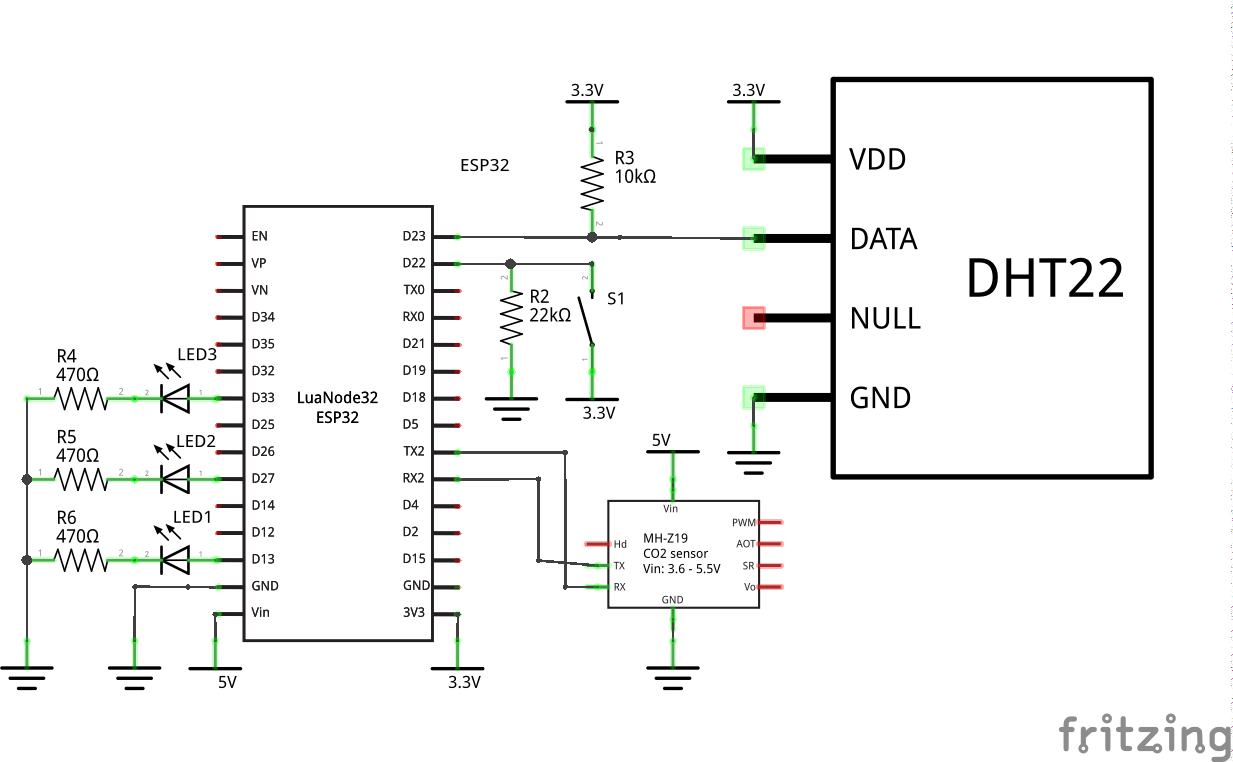
The circuit extends the one described in the previous posts. The DHT22 sensor is still connected to the D23 pin. R3 is a pull-up resistor in case your DHT22 sensor doesn’t have one. The switch S1 still turns on the configuration mode. In this mode, the device starts up a Wi-Fi access point with a web server that allows configuring the device (see the previous posts for details). Let’s see what is new.
The ESP32 board talks to the MH-Z19B sensor via UART (another option is PWN). According to the datasheet, the sensor needs 5V voltage, therefore its Vin pin is connected to the Vin pin of the ESP32 board. When the board is powered via its USB port, the Vin pin provides 5V. The other pins of the sensor are not used.
The LEDs are connected to D13, D27 and D33 pins via current limiting resistors. It’s okay to use resistors with close values (for example, 510 Ohm).
Measuring CO2 with MH-Z19B sensor
The previous posts describe the project structure, interacting with the DHT22 sensor, connecting to Wi-Fi, authentication and sending data to a Google sheet. Here let’s discuss only measuring CO2 level.
The class MHZ19BSensor is responsible for reading data from the MH-Z19B sensor:
The class takes the following parameters:
- TX and RX pins that are connected to the sensor
- An instance of the class
Lightsthat controls the LEDs - A threshold for CO2 level
The method measure() is the main one. First, it sends the read command to the sensor. It’s just a sequence of bytes that’s defined in the datasheet. Then, the method waits for a while to let the sensor measure CO2 and send the measurement back. After reading the data, the method calls the is_valid() routine that makes sure that the returned data is correct by validating its checksum and a few other constraints. The checksum algorithm is described in the datasheet for the sensor. If something went wrong, the method turns on the red LED. The measured CO2 level is represented by high and low components with the 256 base. The actual value is high * 256 + low. Once the CO2 level is successfully calculated, the method checks if it’s higher than the specified threshold. If so, it turns on the yellow LED. Finally, the method returns the measured value.
The project contains many other classes. Most of them described in the previous posts. I also tried to write some comments in the code. The filemain.py brings everything together. It is also an entry point when the device starts.
Deploying the code to the ESP32 board
The project uses MicroPython v1.13. Check out the previous post for other requirements and instructions. The script upload.sh may make life a bit easier. The script reads config options for the device from environment variables and writes them to the file main.conf before uploading it to the board. Here is what the deployment usually looks like:
sh scripts/erase.sh
sh scripts/flash.sh
sh scripts/verify.sh
export SSID=ssid-for-your-wifi
export WIFI_PASSWORD=password-for-your-wifi
export ACCESS_POINT_SSID=esp32-weather-google-sheets
export ACCESS_POINT_PASSWORD=password-for-the-access-point
export GOOGLE_SERVICE_ACCOUNT_EMAIL=your-google-service-account-email
export GOOGLE_SHEET_ID=your-google-sheet-id
sh scripts/upload.sh
Don’t forget to add the following function to your Google sheet:
function TIMESTAMP_TO_DATE(value) {
  return new Date(value * 1000);
}
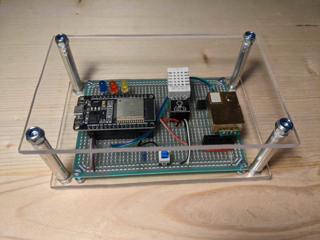
Make it pretty
Google Sheets can draw nice graphs for the measured temperature, humidity and CO2 level. If you’re going to use the device, you may also make a case for it. I just put the board between two acrylic glass sheets. Alternatively, a case may be printed on a 3D printer.


