Transistor delay circuit
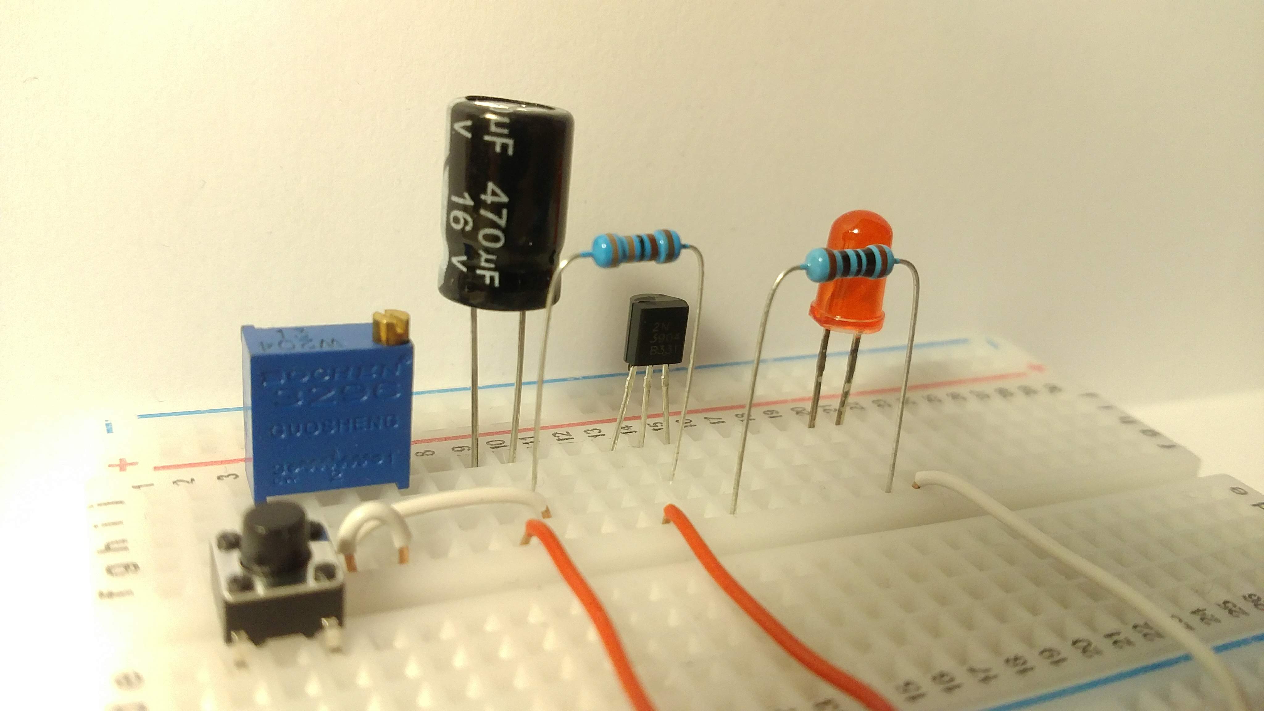
The transistor delay circuit may be helpful to learn some electronics basics. The circuit is pretty simple. It only contains a transistor, a capacitor, several resistors, a switch and an LED. The circuit uses an RC filter to turn an LED on with a little delay. Let’s see how we can choose elements for the circuit, and how the delay depends on parameters of the elements.
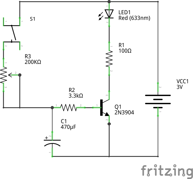
Below you can see the schema. The LED is connected to the collector of the transistor. The resistor R1 limits the current to prevent damaging the LED. The transistor Q1 and the resistor R2 make a switch. The transistor is controlled by the RC filter which is built by the variable resistor R3 and capacitor C1. The RC filter defines the delay.
How the transistor delay circuit works
At first, the capacitor is not charged, and the switch S1 is off. It means that no current comes to the base of the transistor, and the LED is off. If we hold the button S1, the capacitor begins charging. The resistor R3 defines how fast the capacitor charges. The more the resistance of R3 is, the slower the capacitor charges. The RC filter implements a voltage divider. While the capacitor is charging, the voltage across the capacitor grows. It means that the more the capacitor is charged, the more voltage applies to the base of the transistor. After some time, the voltage applied to the base of transistor becomes high enough to open the transistor. The current starts flowing through the transistor, and the LED turns on.
The delay can be adjusted by changing the resistance of the variable resistor R3.
Choosing components for the transistor delay circuit
Let’s see how we can choose elements for the transistor delay circuit.
We use a standard LED which has the following parameters
Next, we use 2N3904 transistor. This is an NPN transistor which has the following parameters according to its datasheet
Choosing a current limiting resistor for an LED
Let’s calculate the value of the resistor R1 which limits the current for the LED.
The voltage supply is 3V. Let’s set the LED current to be 10mA = 0.01A which is less than the maximum allowed current for the LED. This current should be enough to turn the LED on. The LED current is also the collector current.
Now we can apply Ohm’s law to calculate R1:

We can pick up a standard resistor of 100 Ohm.
Choosing a base resistor for a transistor
First, let’s calculate the base current which keeps the transistor open
To make sure the transistor turns on fully, let’s add a factor of two for safety and use a base current of 0.7mA = 0.0007A.
Now we can apply Ohm’s law and calculate R2:

We can pick up a standard resistor of 3.3 KOhm.
How an RC filter defines a delay
The delay is related to the charging time of the capacitor C1. The charging time of the capacitor is related to the product of R3 and C1:

It is the time required to charge the capacitor, through the resistor, from an initial charge voltage of zero to approximately 63.2% of the value of an applied voltage.
The rise time from 20% to 80% can be calculated as the following

If we the capacitor C1 is 470 mkF, and the resistor R3 is 200 KOhm, then the approximate maximum delay is going to be

Note that the LED actually turns on much faster. It happens because the transistor starts opening even before the capacitor is charged to 80%. After some time, once the voltage on the base is high enough, the collector current starts slightly growing. As a result, the LED starts turning on.