Reading a photoresistor on ESP32 with MicroPython
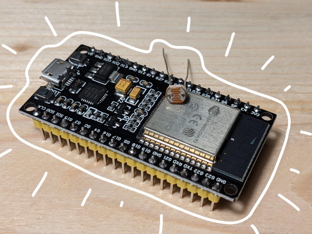
A photoresistor or a light-dependent resistor (LDR) is a resistor that changes its value (resistance) depending on light intensity. More precisely, when light falls upon it, the resistance decreases. It is normally used as a light or dark detector. For example, it may be used in a circuit that turns lights in a room on when it gets dark. Let’s see how we use a photoresistor with ESP32 and MicroPython.
by Alena Penkova
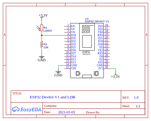
Circuit for photoresistor and ESP32
Here is a list of components we need:
- ESP32 development board
- A light dependent resistor (LDR)
- 10 KOhm resistor
- Breadboard
- Wires
The circuit is pretty simple. A photoresistor R1 is connected to the pin D34 with a pull-down resistor R2. We’re going to measure the voltage on the pin is going to change when the light intensity changes. To do that, the pin should support analog reading. In other words, it needs to be an ADC pin (Analog to Digital Converter). The pin D34 is exactly this kind of pin, according to the datasheets.
The board is going to be powered via USB.
Reading a photoresistor with MicroPython
MicroPyhon offers the class ADC that reads analog values from a pin. The class just take a pin number. Then, values can be read by calling the method ADC.read(). The method returns a number from 0 to 4095. In the default configuration, an instance of ADC expects voltages from 0V to 1V on the pin. If the voltage is above 1V, then the method will return 4095. However, it’s possible to increase the supported voltage range by calling the method ADC.atten().
The code below reads a value from a photoresistor every 3 seconds:
Let’s take a look at the class LDR. It takes a pin number that is connected to the photoresistor, and a desired range [min_value, max_value] for returned values. The constructor checks the parameters and initializes a new ADC. The method read() returns a raw value from the ADC (from 0 to 4095). The method value() calls the method read() and then maps the returned raw value to the desired range [min_value, max_value].
Uploading MicroPython and the code to ESP32
The MicroPython firmware and the code are available on GitHub:
git clone https://github.com/artem-smotrakov/esp32-ldr
To flash the firmware and upload the code, we’ll need several tools:
esptoolfor uploading MicroPython to ESP32mpfshellfor uploading files to ESP32minicomfor connecting to ESP32 for debugging purposes
The steps below work on Linux (I tested in on Ubuntu 18 and 20). On Windows or Mac, it may or may not work.
Note that some ESP32 development boards require pressing the EN button while holding the Boot button for switching the board to the mode for erasing or uploading firmware. Do it before erasing, writing or verifying the firmware.
First, erase the old firmware on the ESP32:
esptool.py --port /dev/ttyUSB0 erase_flash
Next, upload MicroPython v1.13:
esptool.py \
    --chip esp32 \
    --port /dev/ttyUSB0 \
    --baud 460800 \
    write_flash -z 0x1000 esp32-idf3-20200902-v1.13.bin
Then, you may want to verify it:
esptool.py \
    --chip esp32 \
    --port /dev/ttyUSB0 \
    --baud 460800 \
    verify_flash 0x1000 esp32-idf3-20200902-v1.13.bin
Then, upload the code to the board:
mpfshell \
    -n -c \
    "open ttyUSB0; \
    lcd src; mput .*\.py;"
By the way, the directory scripts contains scripts that also do the job.
Finally, you can connect to the board with minicom and see the measurements:
minicom --device /dev/ttyUSB0 -b 115200
The output is going to look like something like this:
value = 18.92552
value = 18.87668
value = 5.006105
value = 18.63248
Try covering the photoresistor with a hand or putting more light on it. See how the values change.