Getting started with ESP8266 and MicroPython
I like the idea of Internet of Things (IoT) which is becoming so popular. We have everything connected to the Internet: TVs, printers, fridges, cars, even teeth brushes, etc. We already have botnets which consist of IoT devices, and are used for massive DDoS attacks. I personally prefer calling it “Internet of Shit” because sometimes it’s not clear why some devices connect to the Internet. By the way, there is a twitter called “Internet of Shit”. I highly recommend to follow.
Using those fancy IoT devices is fun. Furthermore, sometimes such devices are even helpful. But it’s more fun to participate more actively. For example, you can create your own IoT device with blackjack and hookers. God bless those people who developed ESP8266 boards which now allow everybody to build their own IoT devices. As you may know, ESP8266 boards are extremely cheap. And I would say they are relatively easy to use (especially if you know about Google).
I was going to try ESP8266 controllers for long time. Finally, I did it, and want to share my experience in hope it may be useful. I found a lot of articles about ESP8266 and NodeMCU firmware which allows you to run Lua scripts on your ESP8266 board. That’s cool, but the problem is that I don’t know anything about Lua language. Another problem is that I am lazy in this time of year, so I didn’t want to learn Lua. But luckily I know Python a little bit, and there is MicroPython project which allows you to run Python scripts on embedded devices including ESP8266.
Here is a tutorial how to get started with ESP8266 and MicroPython.
Русская версия - Как запустить MicroPython на ESP8266
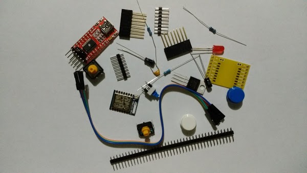
Hardware: ESP8266 ESP-07 and other little things
If I remember correctly, there are about 12 types of ESP8266 boards. I used ESP-07 board which looks like this:
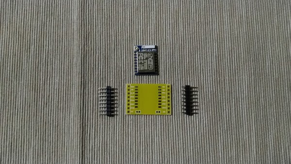
The easiest way is to buy it on AliExpress or DX. I would recommend to order an adapter place (see above) which makes it much easier to work with the board.
I ordered a couple of ESP8266 boards on AliExpress. I actually ordered them twice from two different sellers, and noticed that GPIO4 and GPIO5 pins may be are exchanged:
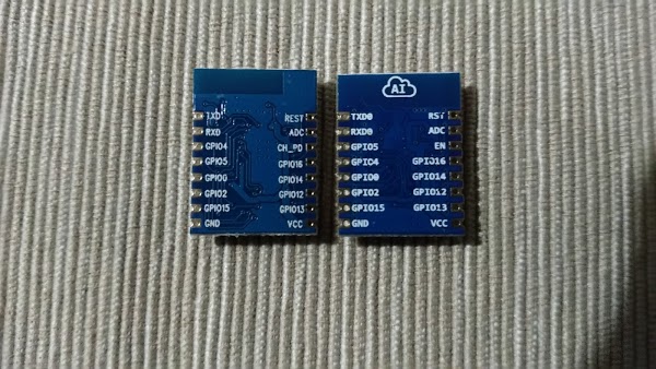
Not sure if that’s a mistake in markup. The Internet says it is, but I have not checked that. I just used the one with markup that matched with the markup on the adapter plate.
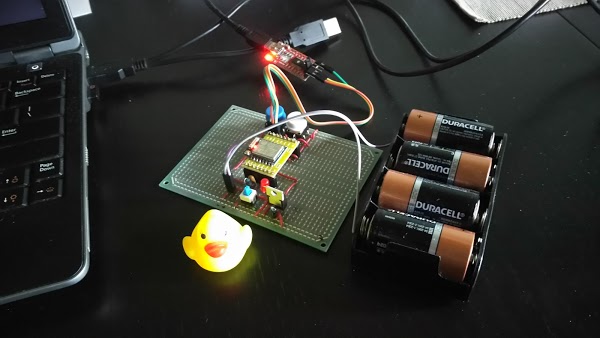
Here is a circuit I used:
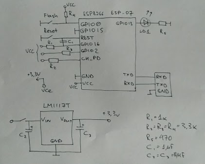
Here you can see ESP8266 ESP-07 board in the center and something else:
FlashandResetbuttons let you switch your board in a couple of modes. ESP8266 boards has two modes which I know about: bootloader mode and flash startup mode. The bootloader mode allows you to flash your board via UART port (see TXD and RXD pins). The flash startup mode is a usual mode when the board runs it’s firmware after it started.- UART interface - see TXD and RXD pins which connect ESP8266 with PC.
- LD1 is an LED which is connected to GPIO13 with a current limiting resistor (yep, we’re going to drive an LED).
- Some other stuff around GPIO pins which I’ll try to explain below.
- A voltage regulator based on LM1117T.
As I mentioned earlier, we are going to use two modes: bootloader mode and flash startup mode. The board will be switched to the bootloader mode if you put low level on GPIO0 and GPIO15, high level on GPIO2, and reset the board. It means that you need to hold Flash button, press Reset button while holding Flash button, and finally release Flash button.
At first, I found a couple of simpler circuits on the Internet:
- No R4 resistor.
- GPIO15 connected to
Flashbutton. - No R3 resistor, GPIO2 is not used (no high level on this port).
But it didn’t work. I could flash the board (see below how), but when I connected to the flashed board via USB-Serial converter, I couldn’t see Python prompt. I tried to reset the board while connected via terminal, and it printed out some garbage to the terminal. I searched on the Internet, and found that it might mean that the board didn’t switch to flash startup mode, and is still in bootloader mode. Then, I found a note about GPIO2, added R4, made GPIO15 to have low level always, and it worked.
You may notice that REST and GPIO16 pins are connected to C1 and R1. I found this on the Internet, it allows the ESP8266 to reset itself after entering low-power sleep mode. I didn’t get time to read more about it, but added just in case.
I’ll provide all links in the end if you are interested in details.
There is a voltage regulator on the circuit. I have read that it’s better to use a separate power supply for ESP8266. I just built a simple voltage regulator on LM1117T which gives stable 3.3V.
I’ll also need a USB-Serial adapter to connect your ESP8266 with PC (a small red board on the picture below). It’s cheap, and you can buy it on AliExpress as well.
Here is how it looks:
Flashing ESP8266 with MicroPython
As I mentioned earlier, I used MicroPython on ESP8266. Latest firmwares can be downloaded here:
http://micropython.org/download/#esp8266
They provide stable builds more than 512K, daily builds more than 512K, and daily builds less than 512K (just wondering, why they don’t have stable builds less than 512K). You should select the firmware depending on how much flash memory your ESP8266 has. When I ordered my ESP8266, I didn’t pay attention on amount of flash, and now I have only 512K. So, I could use only daily builds which are less than 512K. If you don’t know how much flash your ESP8266 has, just try stable builds which are more than 512K. It’s going to report a error if there is no enough memory.
UPDATE: There may be some troubles with the firmware which fits 512K, see Problems with running MicroPython on ESP8266 with 512K. So, better to get a board with more than 512K of flash.
I used esptool to upload the firmware on ESP8266. You can install it with pip or just clone it from https://github.com/espressif/esptool. I have heard that esptool supports only Python 2, so be careful.
Let’s flash ESP8266. First, it’s better to erase flash on your ESP8266. It can be done with a command like the following:
sudo esptool --port /dev/ttyUSB0 erase_flash
Next, you need to switch it to the bootloader mode (see above). You have to do that each time when you want to flash your board again - it automatically tries to switch to the normal mode after flashing. Here is a command which can be used to upload the firmware:
sudo esptool --port /dev/ttyUSB0 --baud 460800 \
    write_flash --flash_size=detect 0 \
    esp8266-512k-20170212-v1.8.7-213-gaac2db9.bin
Oh yes, that’s for Linux. On Windows it may look like a little different. Don’t forget to use correct file name. Finally, you may want to verify flashed firmware with the following command (don’t forget to switch your board to the bootloader mode again):
sudo esptool --port /dev/ttyUSB0 --baud 460800 \
    verify_flash --flash_size=detect 0 \
    esp8266-512k-20170108-v1.8.7.bin
Here is how it normally looks:
$ sudo esptool --port /dev/ttyUSB0 erase_flash
esptool.py v2.0-beta1
Connecting.....
Detecting chip type... ESP8266
Uploading stub...
Running stub...
Stub running...
Erasing flash (this may take a while)...
Chip erase completed successfully in 1.3s
Hard resetting...
$ sudo esptool --port /dev/ttyUSB0 --baud 460800 write_flash --flash_size=detect 0 esp8266-512k-20170108-v1.8.7.bin
esptool.py v2.0-beta1
Connecting....
Detecting chip type... ESP8266
Uploading stub...
Running stub...
Stub running...
Changing baud rate to 460800
Changed.
Attaching SPI flash...
Configuring flash size...
Auto-detected Flash size: 512KB
Flash params set to 0x0000
Compressed 500608 bytes to 330679...
Wrote 500608 bytes (330679 compressed) at 0x00000000 in 7.5 seconds (effective 536.9 kbit/s)...
Hash of data verified.

Leaving...
Hard resetting...
$ sudo esptool --port /dev/ttyUSB0 --baud 460800 verify_flash --flash_size=detect 0 esp8266-512k-20170108-v1.8.7.bin
esptool.py v2.0-beta1
Connecting....
Detecting chip type... ESP8266
Uploading stub...
Running stub...
Stub running...
Changing baud rate to 460800
Changed.
Attaching SPI flash...
Configuring flash size...
Auto-detected Flash size: 512KB
Flash params set to 0x0000
Verifying 0x7a380 (500608) bytes @ 0x00000000 in flash against esp8266-512k-20170108-v1.8.7.bin...
-- verify OK (digest matched)
Hard resetting...
If everything went smoothly, you should have your ESP8266 with MicroPython onboard. Try to connect to your ESP8266 via terminal. I use minicom on Linux:
sudo minicom --device /dev/ttyUSB0 -b 115200
Note that you should use 115200 baud rate. Reset the board if necessary. And you may be interested in exiting minicon. It’s not that obvious. Type Ctrl-A and then Q.
You should see Python prompt:
MicroPython v1.8.7 on 2017-01-08; ESP module with ESP8266
Type "help()" for more information.
>>>
Driving an LED on ESP8266 with MicroPython
And finally, let’s turn on our favorite LED:
MicroPython v1.8.7 on 2017-01-08; ESP module with ESP8266
Type "help()" for more information.
>>> from machine import Pin
>>> pin = Pin(13, Pin.OUT)
>>> pin.high()
>>> pin.low()
>>>
Have fun!
Links:
- http://www.esp8266.com/wiki/doku.php?id=esp8266-module-family#esp-07
- https://docs.micropython.org/en/latest/esp8266/esp8266/tutorial/intro.html
- https://learn.adafruit.com/micropython-basics-how-to-load-micropython-on-a-board/esp8266
- http://www.agcross.com/2015/09/the-esp8266-wifi-chip-part-3-flashing-custom-firmware/
- https://forum.micropython.org/viewtopic.php?t=2277
- https://zoetrope.io/tech-blog/esp8266-bootloader-modes-and-gpio-state-startup
- http://docs.micropython.org/en/latest/wipy/library/machine.Pin.html